


|
|||||||||||||||
| Group5: | 6 blaze gratings having periods of 10µm, 20µmģ to 60µm: Each grating has 4 periods, and has 20 gray levels in each period. D = 0.12 + 0.0526i, where i = 0, 1, 2 . . . . . 19. |
| Group 6: | 6 blaze gratings having periods of 50µm, 100µm, 200µm, 300µm, 400µm, and 500µm: Each grating has 4 periods, and has 100 gray levels in each period. D = 0.12 + 0.0101i, where i = 0, 1, 2 . . . . . 99. |
| Part III: | With this portion of the calibration
plate, HEBS-glass users can determine the optical density (OD) range of
a gray scale mask that is most appropriate for a particular device fabricated
with existing in-house processes and equipment for photolithography and
ion beam etching. This part contains two sets of test patterns that
are arranged as follows:
|
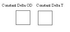
| Each of the two
test patterns has nine optical density ranges. There are 20 gray
levels within each of the nine optical density ranges. Within the
test pattern on the left, the 20 OD values in each of the nine ranges vary
in intervals of constant delta OD. The test pattern on the right
has the same optical density ranges but vary in intervals of a constant
delta T.
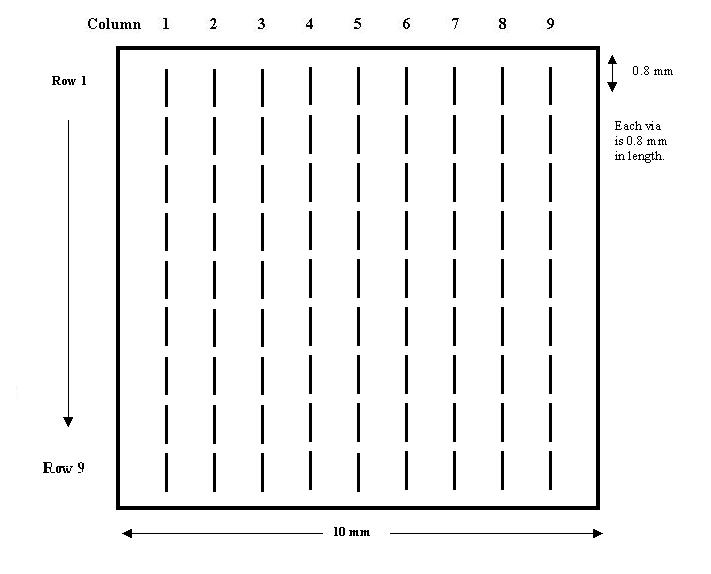
Each test pattern is composed of a 9x9 array of via structures that are 800 microns in length (See Diagram I). The OD range is consistent across a row, whereas the width and gap of the via structure is consistent down a column. Table I exhibits the values of minimum and maximum ODÆs within each of the nine OD ranges. Table II displays the dimensions of the via structures within a column. Diagram 2 defines the via gap and via width. Note that when the via gap is 0 µm, the via structure is actually a V-groove. For more detailed reference, the OD values corresponding
to the twenty gray levels in each of the nine rows for test patterns of
constant delta OD is listed in Table III. Similarly, the OD values
of the twenty gray levels in each of the nine rows for test patterns of
constant delta T is listed in Table IV.
|
|
| Instructions
for viewing mask patterns under an optical microscope: Please
view mask patterns in the HEBS-glass under a microscope in transmission
mode (i.e. using the bottom light); the mask pattern has little or
no contrast in a reflection mode (i.e. using the top light) because the
reflectance of HEBS-glass is 4% in both clear and e-beam darkened areas.
Instructions for handling and storage:
Since the mask pattern is inside the glass, HEBS-glass masks can be washed
like a quartz glass substrate, using any solvent or acid (except HF).
HEBS-glass masks should be kept at room temperature. Humidity levels
from 0 to 100% do not affect HEBS-glass masks.
|
|
| Diagram 1. Layout of one test pattern
|
|
Next Page |
|
Company | Technology | Products | Online Help | Contact