     |
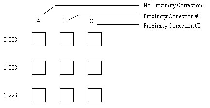
Part V: A 2mm x 2mm blazed grating having a 20 micron period is designed with two variable parameters in a 3 x 3 matrix depicted below. The first variable parameter is the optical density range. Three optical density ranges: 0.223 to 0.823, 0.223 to 1.023, and 0.223 to 1.223 are identified by labeling the values of maximum OD. The second variable parameter is proximity corrections aiming to minimize the width of backward slope or the rounding of the triangular cross-section within a blazed grating period. The grating has 20 gray levels within each period.
Part VI: 2 sinusoidal gratings, each of 1mm x 1mm in size. The first has a period of 10m m and the second has a period of 20m m. Each sinusoidal grating has 20 gray levels. The equation for the sinusoidal spatial modulation of the transmittance goes as T=(sinq +1)(D T)/2, where q =6.2832X/P, X = position of a gray level within a grating period. Period P is 10m m and 20m m for the first and the second grating respectively, and D T=Tmax-Tmin. The transmittance for both of the gratings varies from 59.8% to 2.5%. This range of transmission values corresponds to an OD range of 0.223 to 1.599. The superior properties of sinusoidal test patterns and arrays of density wedges in HEBS glass encourages new as well as traditional applications such as: beam shaping filters, spatial filtering, waveguides, and MTF evaluation of materials, lenses, cameras, devices and electro-optical systems.
Part VII: An array of refractive microlenses having a 100% fill factor. Each lenslet is 50m m x 50m m and is written with 32 gray levels. The OD range of the 32 gray levels is 0.129 to 1.017.
Part VIII: Exemplary 4 x 5 subarrays selected from an array of microlenses having a variable lens parameter within the array. In this example, the lenslets within each subarray has a unique compound tilt. The facet centerline angle of each lenslet is the variable parameter and is a function of distance r from the optical center of the lens array. The range of facet centerline angles displayed is from 4.277 to 17.23 degrees. Each lenslet is 57m m x 57m m and is written with 20 gray levels. The lens sag and thus the OD range of the gray levels within a lenslet increase with an increasing facet centerline angle. HEBS-glass enables users to create new as well as traditional designs of microlens arrays.
Instructions for viewing mask patterns under an optical microscope: Please view mask patterns in the HEBS-glass under a microscope in a transmission mode (i.e. using the bottom light); the mask pattern has little or no contrast in a reflection mode (i.e. using the top light) because the reflectance of HEBS-glass is about 4% in both clear and e-beam darkened areas. Instructions for handling and storage: Since the mask pattern is inside the glass, HEBS-glass masks can be washed like a quartz glass substrate, using any solvent or acid (except HF). Strong base solution may cause pits in the surface of HEBS-Glass or any silicate glass. HEBS-Glass masks should be kept at room temperature. Humidity levels from 0 to 100% do not affect HEBS-glass masks.
|
| Company | Technology | Products | Online Help | Contact |